Thursday, June 28, 2012

[OpenFlow] Update and Setup TP-LINK TL-WR1043ND for OpenFlow

Currently the version of TP-LINK TL-WR1043ND which I can get in Taiwan is "(TW) ver:1.0" instead of ver:1.8 I want. But, fortunately, after asking the vendor about this issue, he responds that there is no difference in hardware between "(TW) ver:1.0"and ver:1.8 or ver:1.4. That is a good news to me though. The following items are my steps to  transform original TP-LINK TL-WR1043ND to OpenFlow-enabled switch. Most of information is from http://www.openflow.org/wk/index.php/Pantou_:_OpenFlow_1.0_for_OpenWRT

1. Update firmware on your device
Installing OpenWrt this web site has 4 methods for us to do updating. Because my TL-WR1043ND is brand new one, I choose the simplest of method 1: via orginal firmware.
  • Download  image  (v1.8)
  • Change your PC ip address to 192.168.1.2
  • Connect to the switch with LAN port
  • Browse http://192.168.1.1
  • Choose function "update firmware" with the image bin file


2. Modify Configuration 
  • Login  to 192.168.1.1 using telnet
  • Setup your controller ip address (my controller ip is 192.168.1.244)
    • vi  /etc/config/openflow
        config 'ofswitch'
                option 'dp' 'dp0'
                option 'dpid' '000000000011'
                option 'ofports' 'eth0.0 eth0.1 eth0.2 eth0.3 '
                option 'ofctl' 'tcp:192.168.1.244:6633'
                option 'mode'  'outofband'


  • Setup your network configuration and setup this switch ip address (my switch ip is 192.168.1.11)
    • vi /etc/config/network and paste the following lines
        config 'switch'
                option 'name' 'rtl8366rb'
                option 'reset' '1'
                option 'enable_vlan' '1'
                option 'enable_learning' '0'
               
        config 'switch_vlan'
                option 'device' 'rtl8366rb'
                option 'vlan' '1'
                option 'ports' '1 5t'
       
        config 'switch_vlan'
                option 'device' 'rtl8366rb'
                option 'vlan' '2'
                option 'ports' '2 5t'
       
        config 'switch_vlan'
                option 'device' 'rtl8366rb'
                option 'vlan' '3'
                option 'ports' '3 5t'
       
        config 'switch_vlan'
                option 'device' 'rtl8366rb'
                option 'vlan' '4'
                option 'ports' '4 5t'
       
        config 'switch_vlan'
                option 'device' 'rtl8366rb'
                option 'vlan' '5'
                option 'ports' '0 5t'
       
        config 'interface' 'loopback'
                option 'ifname' 'lo'
                option 'proto'  'static'
                option 'ipaddr' '127.0.0.1'
                option 'netmask' '255.0.0.0'
               
        config 'interface'
                option 'ifname' 'eth0.1'
                option 'proto' 'static'
       
        config 'interface'
                option 'ifname' 'eth0.2'
                option 'proto' 'static'
       
        config 'interface'
                option 'ifname' 'eth0.3'
                option 'proto' 'static'
       
        config 'interface'
                option 'ifname' 'eth0.4'
                option 'proto' 'static'
       
        config 'interface'
                option 'ifname' 'eth0.5'
                option 'proto' 'static'
                option 'ipaddr' '192.168.1.11'
                option 'netmask' '255.255.255.0' 

 3. Restart networking to enable your changes
  • /etc/init.d/network restart
4. Verify (My case is for Trema Controller)
  • Connect your Ethernet cable from LAN port to WAN port
  • Start any kind of Trema app
    • for instance : ./trema run ./objects/examples/learning_switch/learning_switch
  • Show switch description
    • TREMA_HOME=`pwd` ../apps/show_description/show_description
    • And then we can get the information as follows:
        Manufacturer description: Stanford University
        Hardware description: Reference Userspace Switch
        Software description: 1.0.0
        Serial number: None
        Human readable description of datapath: OpenWrt pid=1933
        Datapath ID: 0x11
        Port no: 1(0x1)(Port up)
          Hardware address: 90:f6:52:89:c9:d0
          Port name: eth0.1
        Port no: 2(0x2)(Port up)
          Hardware address: 90:f6:52:89:c9:d0
          Port name: eth0.2
        Port no: 3(0x3)(Port up)
          Hardware address: 90:f6:52:89:c9:d0
          Port name: eth0.3
        Port no: 4(0x4)(Port up)
          Hardware address: 90:f6:52:89:c9:d0
          Port name: eth0.4

Wednesday, June 27, 2012

[OpenFlow] Summary of some current OpenFlow Related Articles


1. http://blog.ioshints.info/2011/11/openflow-enterprise-use-cases.html
This article discusses enterprise use cases in OpenFlow
  • There are four functions you can easily implement with OpenFlow (Tony Bourke wrote about them in more details)
    • packet filters – flow classifier followed by a drop or normal action
    • policy based routing – flow classifier followed by outgoing interface and/or VLAN tag push
    • static routes – flow classifiers using only destination IP prefix
    • NAT – some OpenFlow switches might support source/destination IP address/port rewrites.

2. http://routerjockey.com/2011/11/02/nec-and-programmableflow-switching/
This article writer give some information and comments about NEC programmableflow because he joined NEC presenting at Networking Tech Field Day 2


3. http://blog.ioshints.info/2011/11/openflow-deployment-models.html#of_native
This article provides four different models for OpenFlow deployment have already emerged:
  • Native OpenFlow
    • The controller performs all control-plane functions, including running control-plane protocols with the outside world. 
    • This model has at least two serious drawbacks even if we ignore the load placed on the controller by periodic control-plane protocols:
      • The switches need IP connectivity to the controller for the OpenFlow control session. 
      • Fast control loops like BFD are hard to implement with a central controller, more so if you want to have very fast response time.
  • Native OpenFlow with extensions
    • A switch controlled entirely by the OpenFlow controller could perform some of the low-level control-plane functions independently.
    • Using OpenFlow extensions or functionality implemented locally on the switch, you destroy the mirage of the “OpenFlow networking nirvana”-- smart open-source programmable controllers control dumb low-cost switches, busting the “networking = mainframes” model and bringing the Linux-like golden age to every network.
  • Ships in the night
    • Switches have traditional control plane; OpenFlow controller manages only certain ports or VLANs on trunked links. The local control plane (or linecards) can perform the tedious periodic tasks like running LACP, LLDP and BFD, passing only the link status to the OpenFlow controller.
  • Integrated OpenFlow
    •  OpenFlow classifiers and forwarding entries are integrated with the traditional control plane. For example, Juniper’s OpenFlow implementation inserts compatible flow entries (those that contain only destination IP address matching) as ephemeral static routes into RIB (Routing Information Base)
    •  From my perspective, this approach makes most sense: don’t rip-and-replace the existing network with a totally new control plane, but augment the existing well-known mechanisms with functionality that’s currently hard (or impossible) to implement.


Monday, June 18, 2012

[OpenFlow] Wildcard Explanation

This article is about flow wildcard for match field. Basically, we can get understood most of them at a glance. But, for  NW_SRC_MASK and NW_DST_MASK they need to do more a little bit math. I only give an example with NW_SRC_MASK because NW_DST_MASK is similar case. Please refer to the following picture:

The position of NW_SRC_MASK is from 8 to 13. If we want to setup a IP subnet mask as 192.168.1.0/24, we should give the value: 001000 (8 bits are wirdcarded). Another example, for instance, 192.168.0.0/16 (16 bits are wirdcarded), the value should be 010000.


/* Flow wildcards. */ enum ofp_flow_wildcards { OFPFW_IN_PORT = 1 << 0, /* Switch input port. */ OFPFW_DL_VLAN = 1 << 1, /* VLAN id. */ OFPFW_DL_SRC = 1 << 2, /* Ethernet source address. */ OFPFW_DL_DST = 1 << 3, /* Ethernet destination address. */ OFPFW_DL_TYPE = 1 << 4, /* Ethernet frame type. */ OFPFW_NW_PROTO = 1 << 5, /* IP protocol. */ OFPFW_TP_SRC = 1 << 6, /* TCP/UDP source port. */ OFPFW_TP_DST = 1 << 7, /* TCP/UDP destination port. */ /* IP source address wildcard bit count. 0 is exact match, 1 ignores the * LSB, 2 ignores the 2 least-significant bits, ..., 32 and higher wildcard * the entire field. This is the *opposite* of the usual convention where * e.g. /24 indicates that 8 bits (not 24 bits) are wildcarded. */ OFPFW_NW_SRC_SHIFT = 8, OFPFW_NW_SRC_BITS = 6, OFPFW_NW_SRC_MASK = ((1 << OFPFW_NW_SRC_BITS) - 1) << OFPFW_NW_SRC_SHIFT, OFPFW_NW_SRC_ALL = 32 << OFPFW_NW_SRC_SHIFT, /* IP destination address wildcard bit count. Same format as source. */ OFPFW_NW_DST_SHIFT = 14, OFPFW_NW_DST_BITS = 6, OFPFW_NW_DST_MASK = ((1 << OFPFW_NW_DST_BITS) - 1) << OFPFW_NW_DST_SHIFT, OFPFW_NW_DST_ALL = 32 << OFPFW_NW_DST_SHIFT, OFPFW_DL_VLAN_PCP = 1 << 20, /* VLAN priority. */ OFPFW_NW_TOS = 1 << 21, /* IP ToS (DSCP field, 6 bits). */ /* Wildcard all fields. */ OFPFW_ALL = ((1 << 22) - 1) };


Friday, June 15, 2012

[Summary] Data Center Network Issues


http://muratbuffalo.blogspot.tw/2010/11/vl2-scalable-and-flexible-data-center.html
The key points from my point of view in this article for Data Center :

Agility:
  • Without agility, each service must pre-allocate enough servers to meet difficult to predict demand spikes, or risk failure at the brink of success. With agility, the data center operator can meet the fluctuating demands of individual services from a large shared server pool, resulting in higher server utilization and lower costs. In order to achieve agility, assigning servers to a service should be independent of network topology.
 Downtime Issue:
  • Still, downtimes can be significant, and with no obvious way to eliminate all failures from the top of the hierarchy, this paper's approach is to broaden (fatten) the topmost levels of the network so that the impact of failures is muted and performance degrades gracefully.
Data center traffic:
  • The paper proposes to use valiant load balancing (vlb) to randomize end-to-end communication paths to cope with volatility and achieve load balancing. In this scheme, the ToR switch randomly chooses an intermediate switch (among many available options) on a per flow basis.
This paper provide an approach of Clos topology.


Wednesday, June 13, 2012

[Demo] OpenFlow GUI demo

Here is a video about OpenFlow GUI demo on a simple topology.
I modified the flow animation so that the flow animation is different from the original one.
Check it out.
http://youtu.be/8r93qgt7VVE

Monday, June 11, 2012

[Tutorial] An example of using juju to deploy cloud services

Before you get started with juju, please refer to the official documens
https://juju.ubuntu.com/docs/getting-started.html
https://juju.ubuntu.com/docs/user-tutorial.html

P.S: When you lunch an instance, be careful about the instance type. Except t1.micro, others will charge you money~~
I strongly suggest to add parameter after juju bootstrap and deploy command as follows:
--constraints "instance-type=m1.micro"
or execute this command:
> juju set-constraints instance-type=t1.micro
For more info about this, please check out this document:
https://juju.ubuntu.com/docs/constraints.html

My environment is using EC2.
> vi .juju/environment.yaml
environments:
  sample:
    type: ec2
    access-key: << your access key >>
    secret-key: << your secret key >>
    control-bucket: juju-0f3b4bce2d944893a74967016c98b903
    admin-secret: 0d748130374946babe1f2531d77620d0
    default-series: precise
    ssl-hostname-verification: true

When you prepare your .juju/environment.yaml ready, you are able to do the following steps to try juju:
> juju bootstrap
> juju deploy wordpress
> juju deploy mysql
> juju add-relation mysql wordpress
> juju expose wordpress

After executing above commands, we can use "juju status" to see what we have now on Amazon EC2:
> juju status
2012-06-11 09:00:26,558 INFO Connecting to environment...
2012-06-11 09:00:43,657 INFO Connected to environment.
machines:
  0:
    agent-state: running
    dns-name: ec2-23-22-111-234.compute-1.amazonaws.com
    instance-id: i-30fa4a49
    instance-state: running
  1:
    agent-state: running
    dns-name: ec2-50-17-117-72.compute-1.amazonaws.com
    instance-id: i-b055eac9
    instance-state: running
  2:
    agent-state: running
    dns-name: ec2-23-22-205-88.compute-1.amazonaws.com
    instance-id: i-de52eda7
    instance-state: running
services:
  mysql:
    charm: cs:precise/mysql-2
    relations:
      db:
      - wordpress
    units:
      mysql/0:
        agent-state: started
        machine: 2
        public-address: ec2-23-22-205-88.compute-1.amazonaws.com
  wordpress:
    charm: cs:precise/wordpress-1
    exposed: true
    relations:
      db:
      - mysql
    units:
      wordpress/0:
        agent-state: started
        machine: 1
        open-ports:
        - 80/tcp
        public-address: ec2-50-17-117-72.compute-1.amazonaws.com
2012-06-11 09:01:18,809 INFO 'status' command finished successfully

From now on, we can check EC2 dashboard and see what instances are there ( it will be the same as the result of "juju status")

Because we do "expose" for wordpress, we have a public address ( ec2-50-17-117-72.compute-1.amazonaws.com) and it looks like as below:

Once you are done with an juju deployment, you need to terminate all running instances in order to stop paying for them.
> juju destroy-environment
WARNING: this command will destroy the 'sample' environment (type: ec2).
This includes all machines, services, data, and other resources. Continue [y/N]y
2012-06-11 09:53:03,181 INFO Destroying environment 'sample' (type: ec2)...
2012-06-11 09:53:10,018 INFO Waiting on 3 EC2 instances to transition to terminated state, this may take a while
2012-06-11 09:53:53,257 INFO 'destroy_environment' command finished successfully


Tuesday, June 5, 2012

[How to] do trouble shooting with LLDP setting on Switch

Let me assume if there is a simple topology here
                              +------------------+
                      Switch  |  172.17.255.254  |
                              +-----+------------+
              +-----------------+   |
      Switch  |   172.17.4.1    |<--+
              +----------+------+
 +--------------+        |
 | Your Server: |        |
 | 172.17.2.200 |<-------+
 +--------------+

A. Make sure Switch and Switch could ping each other
  1. telnet 172.17.255.254
  2. ping 172.17.4.1
B. Make sure that every port should have "management address" checked.

C. Use snmpwalk to check 172.17.255.254 has remote ip address of 172.17.4.1
  • exp: snmpwalk -c public -v2c 172.17.255.254 1.0.8802.1.1.2.1.4.2.1.3
  • if we cannot see the result as follows, it means that the LLDP configuration setting on Switch 172.17.255.254 is wrong. 
         Result: iso.0.8802.1.1.2.1.4.2.1.3.0.4.55.1.4.172.17.4.1 = INTEGER: 2

D. Use snmpwalk to check 172.17.4.1if it has remote ip address of 172.17.255.254
  • exp: snmpwalk -c public -v2c 172.17.4.1 1.0.8802.1.1.2.1.4.2.1.3
  •  if we cannot see the result as follows, it means that the LLDP configuration setting on Switch 172.17.4.1 is wrong.

Saturday, May 26, 2012

[Qt] memory management and implicit sharing

There are some points that we have to know when we program using Qt:

  • The ownership of all child QObjects is transferred to the parent.
    • Automatic deletion by the parent
    • Allocated from the heap (using new)
    • manual deletion is not necessary but it won't cause any problems.
  • All QObjects without a parent must be deleted manually.
  • Pay attention to ownership and responsibilities. Qt does not provide a garbage collection.
Only if you have Classes with QObjects, then child items will be deleted if the parent is deleted:

QObject *parent = new QObject; 
QWidget *child1 = new QWidget(parent); QPushButton *child2 = new QPushButton(parent); delete parent; // child1 and child2 will be deleted automatically!


Implicit sharing (IS)
The following example is about how implicit sharing works when test() returns QList object (on stack). This memory address of "a" is shared to "result" and "a" is not destroyed when method:test() is out of scope.
#include "mainwindow.h" #include "ui_mainwindow.h" #include <QList> #include <QtGui> QList<QString> MainWindow::test() { QList<QString> a; // on stack QList<QString> b = QList<QString>(); // on stack QList<QString> *c = new QList<QString>(); // on heap for (int i = 0; i < 10; i++) { /* if we append a reference of QString, it will consume the memory of the QList Object based on the size of string */ a.append("a_helo:"); a.append(QString::number(i)); b.append("b_helo:"); b.append(QString::number(i)); c->append("c_helo:"); c->append(QString::number(i)); } qDebug() << a << " addres:" << &a; qDebug() << b << " addres:" << &b; qDebug() << *c << " addres:" << c; //delete &b; // we cannot manually free the memory of b or c on stack delete c; // OK return a; // Implicit Sharing } MainWindow::MainWindow(QWidget *parent) : QMainWindow(parent), ui(new Ui::MainWindow) { ui->setupUi(this); /* The memory address of result is same with a object in test() because of implicit sharing */ QList<QString> result = test(); QList<QString> result2; qDebug() << result << " addres:" << &result; qDebug() << result2 << " addres:" << &result2; } MainWindow::~MainWindow() { delete ui; }

Monday, May 14, 2012

[Explanation][Trema] The message mechanism in flow_manager app

I give 2 pictures to illustrate the message mechanism in flow_manager app.

1. Request/Reply message using send_request_message() and send_reply_message()


2. (Received) Message using send_message()

Thursday, May 10, 2012

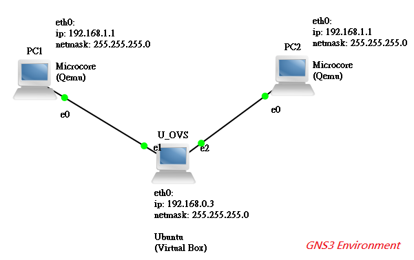
[Open vSwitch] Simply test ovs-ofctl command on GNS3 simulation network


This article is to test ovs-ofctl command on GNS3 simulation network. PC1 and PC2 are  virtual machine on Qemu. U_OVS is emulated with Open vSwitch and an OpenFlow Controller is also on it. Please see the following picture:

1. For how to build the following GNS3 environment, please refer to the URL:
http://brezular.wordpress.com/2011/06/25/part2-openvswich-vlans-trunks-l3-vlan-interface-intervlan-routing-configuration-and-testing/
2. Run > sudo ovs-ofctl show br0

OFPT_FEATURES_REPLY (xid=0x1): ver:0x1, dpid:000008002725cd53
n_tables:1, n_buffers:256
features: capabilities:0x87, actions:0xfff
 1(eth1): addr:08:00:27:95:ef:0b
     config:     0
     state:      LINK_DOWN
     current:    COPPER AUTO_NEG
     advertised: 10MB-HD 10MB-FD 100MB-HD 100MB-FD 1GB-FD COPPER AUTO_NEG
     supported:  10MB-HD 10MB-FD 100MB-HD 100MB-FD 1GB-FD COPPER AUTO_NEG
 2(eth3): addr:08:00:27:25:cd:53
     config:     0
     state:      0
     current:    1GB-FD COPPER AUTO_NEG
     advertised: 10MB-HD 10MB-FD 100MB-HD 100MB-FD 1GB-FD COPPER AUTO_NEG
     supported:  10MB-HD 10MB-FD 100MB-HD 100MB-FD 1GB-FD COPPER AUTO_NEG
 3(eth2): addr:08:00:27:c3:5f:90
     config:     0
     state:      0
     current:    1GB-FD COPPER AUTO_NEG
     advertised: 10MB-HD 10MB-FD 100MB-HD 100MB-FD 1GB-FD COPPER AUTO_NEG
     supported:  10MB-HD 10MB-FD 100MB-HD 100MB-FD 1GB-FD COPPER AUTO_NEG
 LOCAL(br0): addr:08:00:27:25:cd:53
     config:     PORT_DOWN
     state:      LINK_DOWN
OFPT_GET_CONFIG_REPLY (xid=0x3): frags=normal miss_send_len=0

3. After PC1 and PC2 ping each other, run > sudo ovs-ofctl dump-flows br0
NXST_FLOW reply (xid=0x4):
 cookie=0x0, duration=17.125s, table=0, n_packets=14, n_bytes=1372, idle_timeout=5,priority=65535,icmp,in_port=2,vlan_tci=0x0000,dl_src=00:aa:00:3c:24:00,dl_dst=00:aa:00:4d:1d:00,nw_src=192.168.1.2,nw_dst=192.168.1.1,nw_tos=0,icmp_type=8,icmp_code=0 actions=output:3
 cookie=0x0, duration=18.13s, table=0, n_packets=15, n_bytes=1470, idle_timeout=5,priority=65535,icmp,in_port=3,vlan_tci=0x0000,dl_src=00:aa:00:4d:1d:00,dl_dst=00:aa:00:3c:24:00,nw_src=192.168.1.1,nw_dst=192.168.1.2,nw_tos=0,icmp_type=0,icmp_code=0 actions=output:2


p.s:
the script of PC1 configuration
Login is tc without password set.
Assign IP address 192.168.1.1/24 to eth0 and make it persistent after next reboot of Microcore
sudo hostname PC1
sudo ifconfig eth0 192.168.1.1 netmask 255.255.255.0
echo "hostname PC1" >> /opt/bootlocal.sh
echo "ifconfig eth0 192.168.1.1 netmask 255.255.255.0" >> /opt/bootlocal.sh
/usr/bin/filetool.sh -b